
The following table shows the draw and storage tank positions on the various generations of truck models. Use the table to determine the fuel tank location where sensor 1 (draw) should be and where sensor 2 (storage) should be.
NOTE: Locations change, depending on the year of your truck.

- Hook up EZ-Tech to the vehicle’s 9-way diagnostic connector.
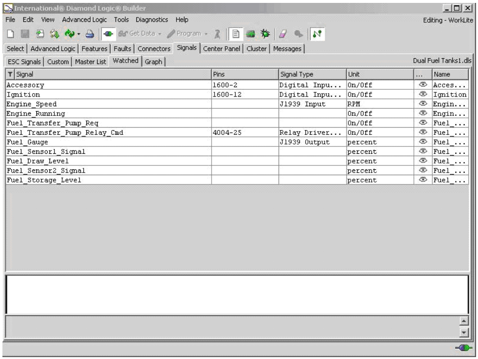
- Open DLB and open a new “Dual Fuel Tanks.dls” session to monitor the parameters necessary to troubleshoot the dual fuel tank transfer pump function. The Watched Signals are shown in Figure 1.
NOTE – The actual fuel sensor readings are displayed as Fuel Sensor 1 Signal (draw) and Fuel Sensor 2 Signal (storage). The ESC conditions these signals over time to allow for fuel sloshing and other transitional effects. The ESC looks at the conditioned signals (Fuel Draw Level and Fuel Storage Level) and uses these values to determine whether or not the fuel transfer pump should be activated. The ESC also conditions the Fuel Sensor 1 Signal and transmits a conditioned signal to be used by the instrument cluster fuel gauge. The importance of this is that the ESC does not react to instant changes in the sensor signals; it waits until the conditioned signals meet the required parameters to activate or deactivate the transfer pump.
3. Verify that the draw tank is in the position listed in Table 1 above. The draw tank should have the fuel supply to the engine, the fuel return line (if equipped with a Cummins or Caterpillar), the transfer pump outlet, and the vent line going into the top of the tank.
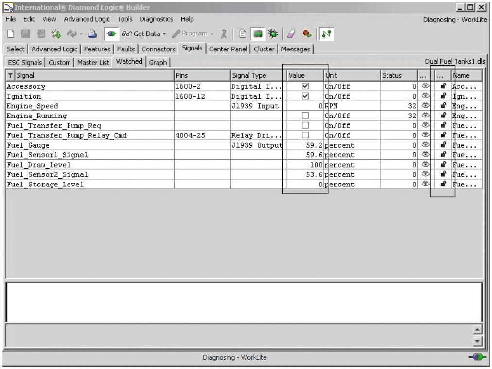
4. Turn the vehicle ignition ON and enter the DLB Diagnostic Mode to show the actual vehicle values as shown in Figure 2. Note that the conditioned signals (Fuel Draw Level and Fuel Storage Level) will always start out at 100% and 0% respectively. The ESC will not begin to condition these values, based on the sensor outputs, until it sees engine RPM
5. Disconnect the fuel level sender connector on the draw tank. If the DLB screen indicates that Fuel Sensor 1 has moved to “0” from its previous position then the wiring to sensor 1 is correct. Reconnect the fuel level sender and verify that the sender output and the actual fuel level in the draw tank are approximately the same.
6. Disconnect the fuel level sender connector on the opposite side tank (should be storage) and verify that DLB shows Fuel Sensor 2 has gone to “0”. Reconnect the fuel level sender and verify that the sender output and the actual fuel level in the storage tank are approximately the same.
7. If both fuel senders pass the above test it verifies that they are wired correctly and operating properly. If the draw tank is not Fuel Sensor 1 and the storage tank is not Fuel Sensor 2 the wiring is reversed and the transfer pump will not work. See Circuit Diagrams at end of procedure for proper connections.
Verify Transfer Pump Function:
- Verify that the vehicle is on and the engine is NOT running.
- Using DLB left click on the “Fuel Transfer Pump Req” Value box and both the Fuel Transfer Pump Req and the Fuel Transfer Pump Relay Cmd boxes should show a check mark indicating ON.
- Listen for the activation of the fuel transfer pump and verify that the pump inlet is coming from the storage tank and the output is going to the draw tank.
- If the pump does not turn on then check the wiring to the ESC, the ESC output on pin 25 of Connector 4004, the pump relay as described in the Introduction of S082503, or the pump itself.
- Left click the “Fuel Transfer Pump Req” padlock symbol and the padlock should open up and remove the checks from the “Fuel Transfer Pump Req” and the “Fuel Transfer Pump Relay Cmd” boxes, the transfer pump should now be off. See Figure 2.
TruckManuals | Diesel Diagnostic Equipment – Your home for all things Diesel Diagnostics